
Home > Products > Wireless Communication > Antennas > Panel Antenna

Electrical Specifications |
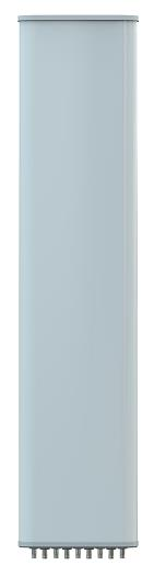
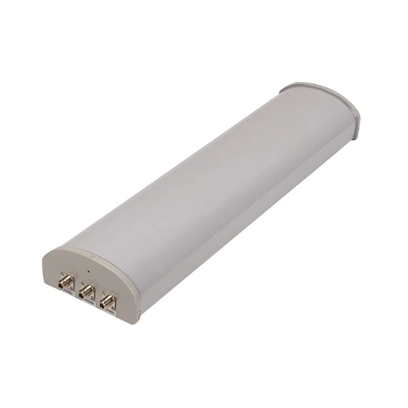
M3D24-90VX14A |
|
Frequency Range (MHz) |
2400~2500 |
|
Polarization |
Vertical/±45° |
|
Gain (dBi) |
14 |
|
Electrical Downtilt (°) |
0 |
|
Half Power Beamwidth (°) |
Horizontal: 90 |
|
Vertical: 15 |
||
First Upper Side Lobe Suppression (dB) |
/ |
|
Front-to-Back Ratio (dB) |
≥23 |
|
Isolation (dB) |
≥25 |
|
Input Impedance (Ω) |
50 |
|
VSWR |
≤1.5 |
|
Maximum Power (W) |
100 |
|
Lightning Protection |
DC Ground |
|
Mechanical & Environmental Specifications |
||
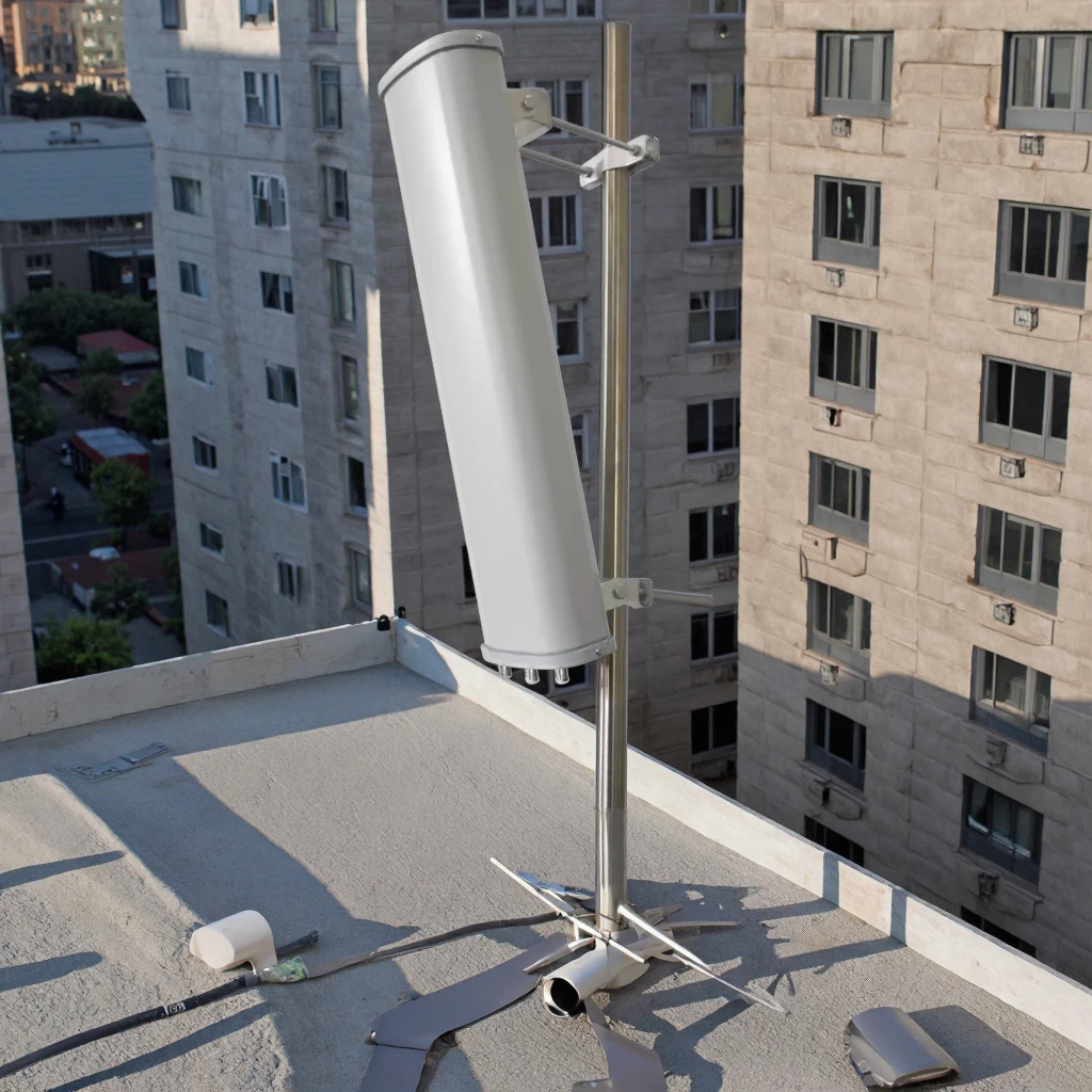
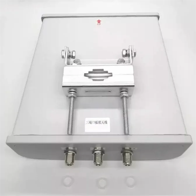
Connector Type |
3×N Female |
|
Connector Position |
Bottom |
|
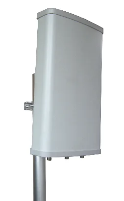
Antenna Dimensions (L×W×H: mm) |
470×167×55 |
|
Antenna Weight (kg) |
1.8 |
|
Radome Material |
UPVC |
|
Radome Color |
Gray |
|
Mechanical Tilt (°) |
0~15 |
|
Operating Temperature (℃) |
-40~60 |
|
Extreme Wind Speed (m/s) |
60 |
|
Pole Diameter (mm) |
35~75 |
|
Mounting Bracket Model |
MK003 |
|