
Home > Products > Wireless Communication > Antennas > Panel Antenna


Electrical Indicators |
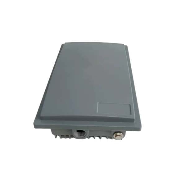
DFC58-20VH18A |
|
Frequency Range (MHz) |
5150~5850 |
|
Polarization |
Vertical/Horizontal |
|
Gain (dBi) |
18 |
|
Electrical Downtilt (°) |
0 |
|
Half Power Beamwidth (°) |
Horizontal: 20 |
|
Vertical: 20 |
||
Port Isolation (dB) |
≥25 |
|
Front-to-Back Ratio (dB) |
≥28 |
|
Input Impedance (Ω) |
50 |
|
Voltage Standing Wave Ratio |
≤2 |
|
Maximum Power (W) |
20 |
|
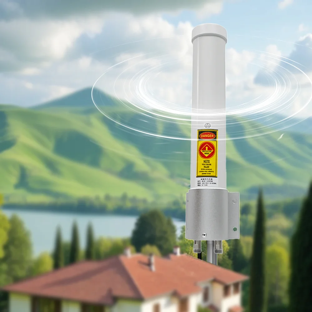
Lightning Protection |
DC Ground |
|
Mechanical and Environmental Indicators |
||
Connector Type |
2×MMCX Elbow or User Specified |
|
Lead Length |
20cm or User Specified |
|
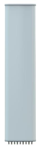
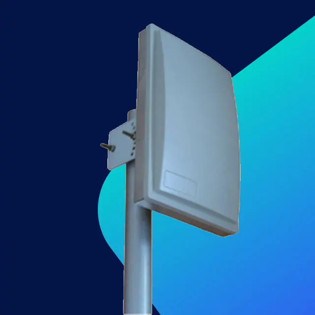
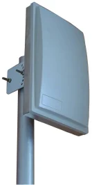
Antenna Size (Length×Width×Thickness: mm) |
320×200×100 (Including Cavity) |
|
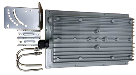
Cavity Size (Length×Width×Thickness: mm) |
265×145×38 (Inner) |
|
Cavity Interface |
1×N Type Extension Port + 1×PG16 |
|
Antenna Weight (kg) |
Approx. 2 |
|
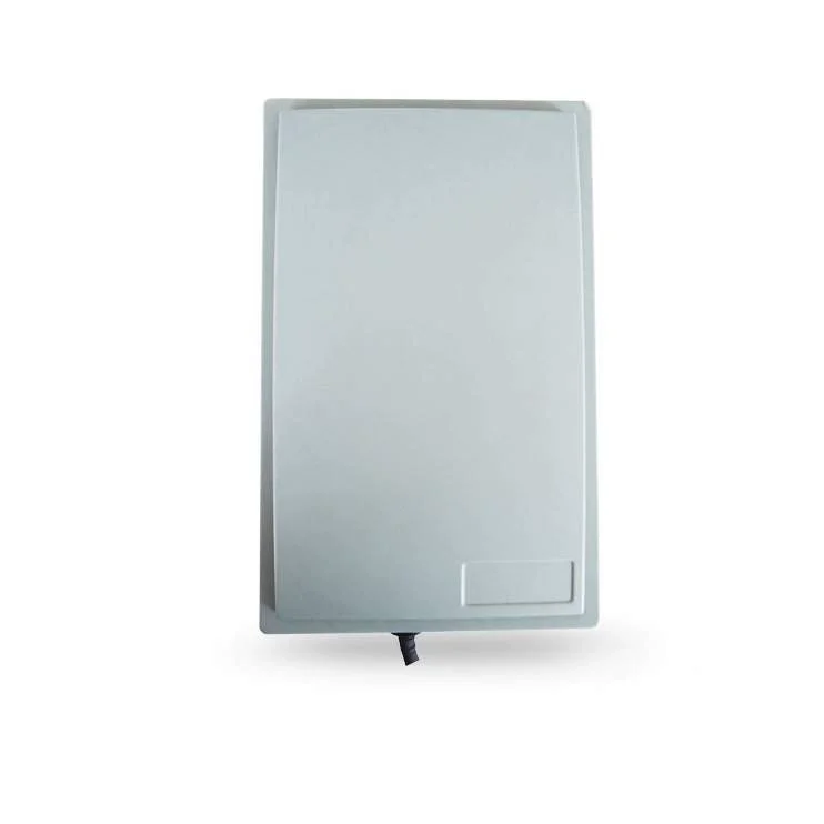
Radome Material |
ABS |
|
Radome Color |
Gray |
|
Cavity Color |
Gray |
|
Mechanical Adjustable Tilt (°) |
0~60 |
|
Operating Temperature (℃) |
-40~60 |
|
Ultimate Wind Speed (m/s) |
60 |
|
Boom Diameter (mm) |
35~50 |
|
Mounting Part Model |
MK004 L-shaped Steel Clamp |
|