
Home > Products > Wireless Communication > Antennas > Panel Antenna


Electrical Indicators |
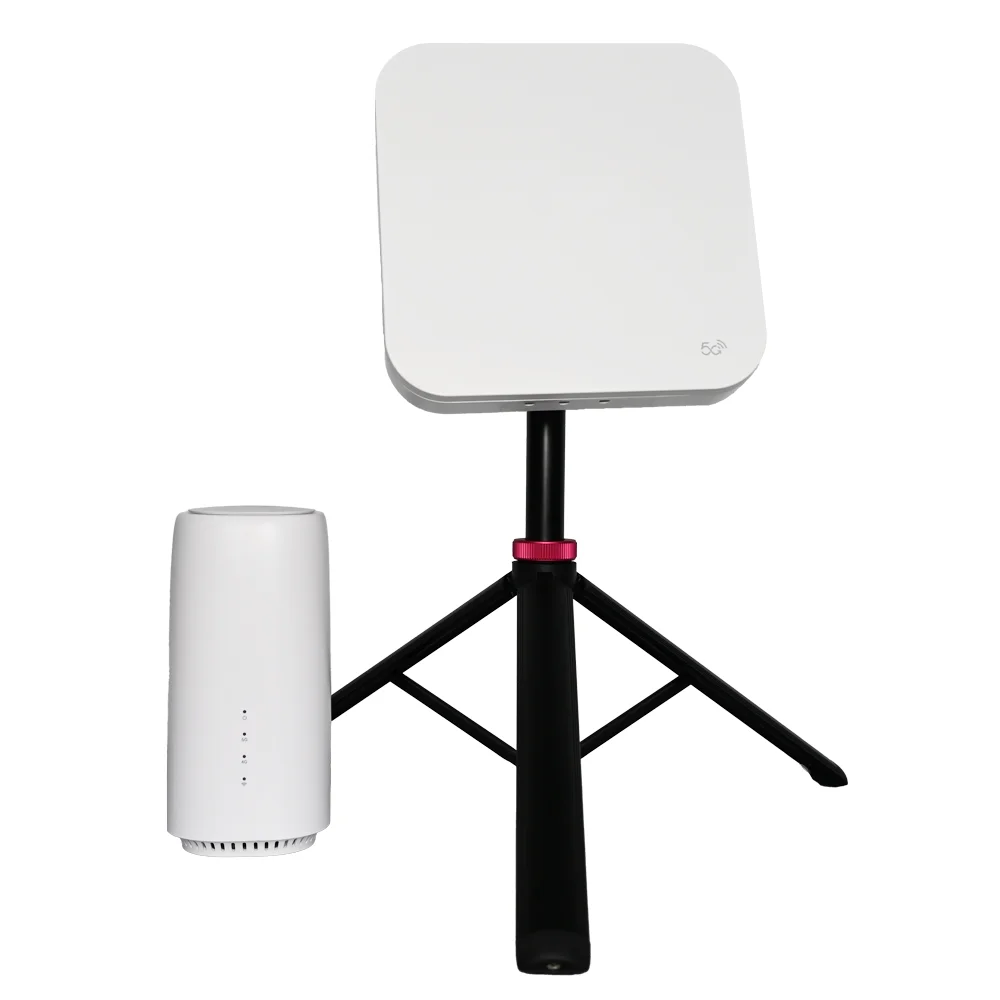
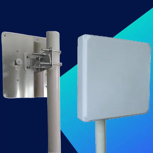
M3D2458-60VH10D |
||
Frequency Range (MHz) |
2400–2500 |
5150–5850 |
|
Polarization |
2×Vertical + 1×Horizontal |
2×Vertical + 1×Horizontal |
|
Gain (dBi) |
10 |
11 |
|
Electrical Downtilt (°) |
0 |
||
Half Power Beamwidth (°) |
H-plane: 60 |
H-plane: 50 |
|
E-plane: 30 |
E-plane: 25 |
||
First Upper Side Lobe Suppression (dB) |
/ |
||
Front-to-Back Ratio (dB) |
≥25 |
||
Input Impedance (Ω) |
50 |
||
Voltage Standing Wave Ratio |
≤2 |
||
Maximum Power (W) |
50 |
||
Mechanical and Environmental Indicators |
Mechanical and Environmental Indicators |
||
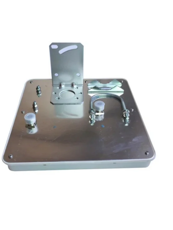
Connector Type |
3×N Female |
||
Lead Length |
/ |
||
Antenna Size (Length×Width×Thickness: mm) |
190×190×40 |
||
Antenna Weight (kg) |
1 |
||
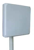
Radome Material |
ABS |
||
Radome Color |
White |
||
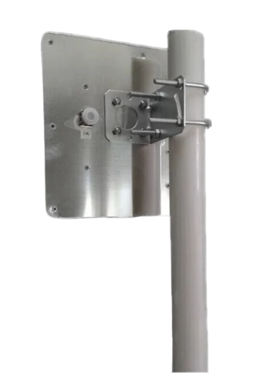
Mechanical Adjustable Tilt (°) |
0–60 |
||
Operating Temperature (℃) |
–40–60 |
||
Ultimate Wind Speed (m/s) |
60 |
||
Boom Diameter (mm) |
35–50 |
||
Mounting Part Model |
MK004A L-shaped Steel Clamp |
||